DFD
Data-flow diagram illustrates the flow of information for processes and systems.
Notation
- External entity: Represented by a noun, they are elements outside the system that emits or receive data.
- Process: Represented by a verb, they are actions that change the data, producing an output.
- Data Store: Represented by a noun, they are elements that store a type of data, like a table in a database.
- Data flow: Represented by the name of the data, they are the route between all the others elements.

Some rules
- DFD diagrams represent only data, no process, actions or operations…
- Process and data store always have minimum 2 data flows: in and out
- All processes must be linked to either another process or a data store.
Levels
Level 0
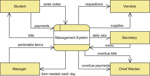
The contextual level is highly abstracted and serve only a resumed overview. It includes:
- All external entities
- Only one process
- No data stores
- Main data flows

Level 1
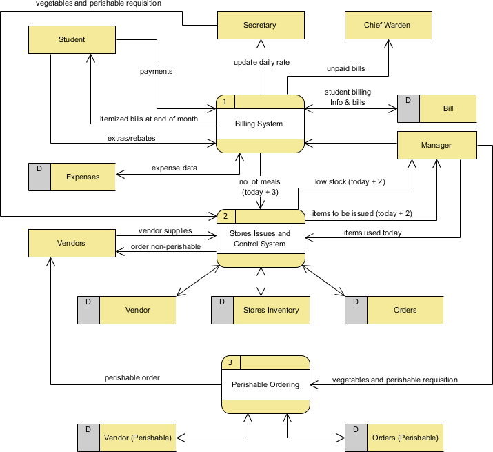
The first level highlight main functions of the system by decomposing the main process into subprocesses. 
Level 2
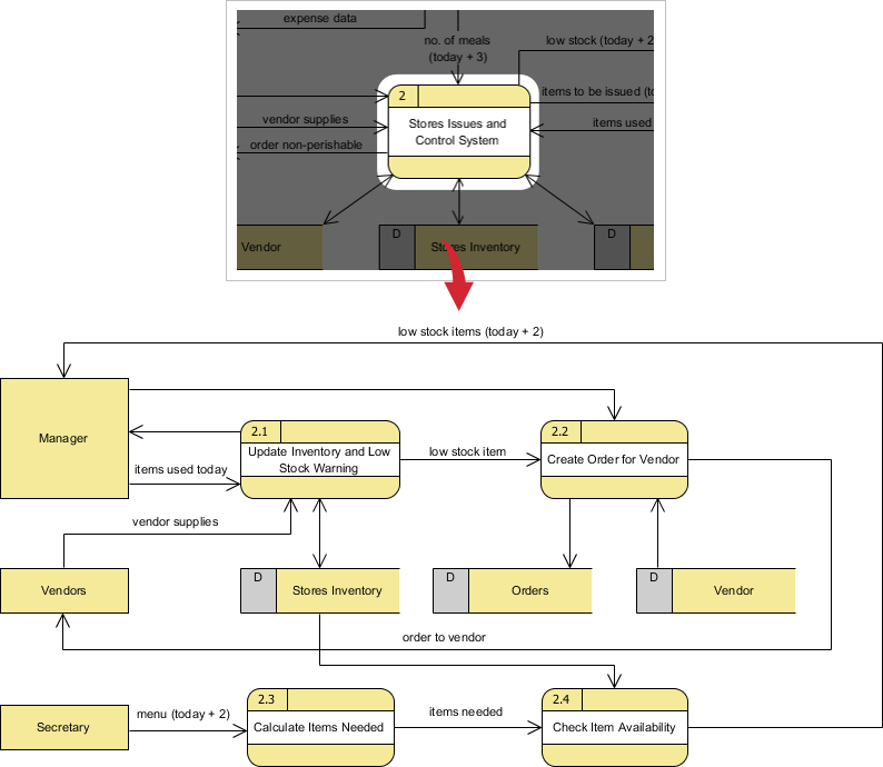
The second level take each processes from level 1 and details it into other incremental subprocess (1.x, 2.x, etc.). 
You can repeat the process and dig deeper in levels, splitting the process into more details, but 1-2 levels are generally enough.
Resources
- What is Data Flow Diagram? – Visual Paradigm